1
Bend feasibility review
Check radius, flange length, reliefs, hole proximity, grain direction, tooling clearance, and collision risk.
Checkpoint
Risky bends and drawing assumptions documented.
Quality System
ISO 9001
Manufacturing Lead Time
Quoted by Scope
500+
Projects Completed
25+
Countries Served
25+
Years Experience
Dongguan
China Factory
Fabex operates a quality management system certified to GB/T 19001-2016 / ISO 9001:2015.
GB/T 19001-2016 quality management system
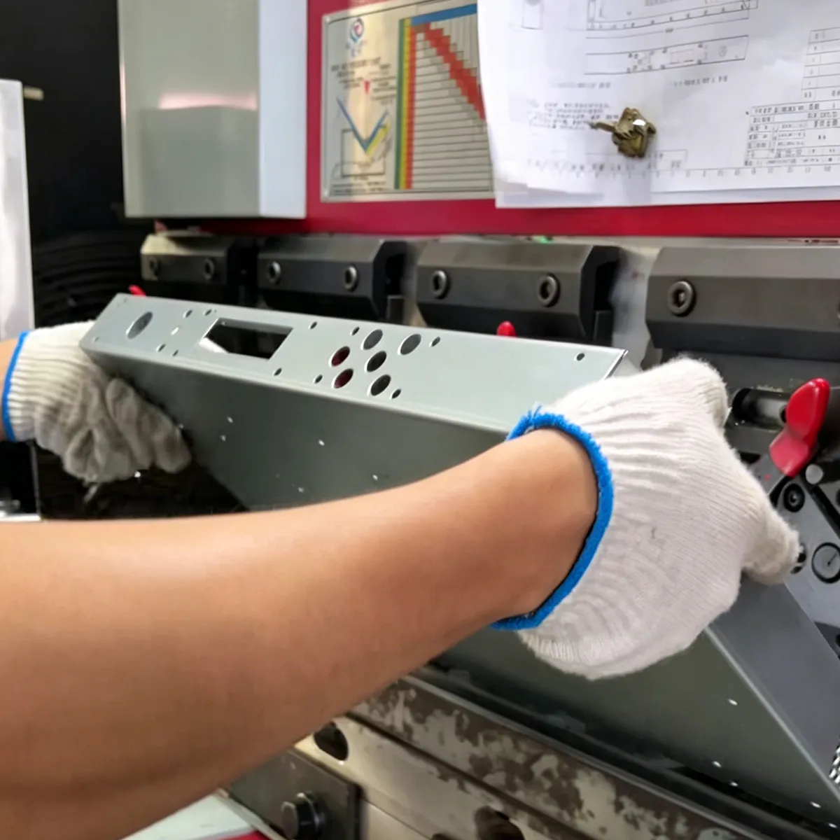
Press-brake capability
Reliable formed parts start with the correct bend radius, tooling access, grain direction, sequence, and tolerance plan.
| Capability | Fabex scope | Engineering checkpoint |
|---|---|---|
| Press capacity | 100-130 tons | Required tonnage changes with material strength, die opening, and bend length. |
| Bend length | Press-brake machine capacity up to 3,200 mm; continuous bends are normally kept at or below approximately 2,000 mm | Longer bends require drawing review because angle consistency, handling, self-weight deformation, part stiffness, material, tooling, and geometry govern acceptance. Long formed parts may need welded or other structural support. |
| Materials and thickness | 0.6-3.5 mm bendable sheet, including drawing-specified grades | Cracking risk depends on temper, grain direction, edge condition, and radius. |
| Radius and angle control | Typical angle tolerance: +/-0.5 to +/-1.5 degrees, depending on material, length, and thickness | Springback compensation and measurement method should be agreed for critical bends. |
| Tooling library | Standard and special tooling reviewed during DFM | Existing tooling can reduce cost if the design permits a compatible radius and access. |
Send your drawing, material, quantity, and delivery target. Our team will review the process route, manufacturability risks, and open questions before quotation.
Forming control
A bend that is individually possible can still be impossible later in the sequence, so the complete formed geometry is reviewed first.
Check radius, flange length, reliefs, hole proximity, grain direction, tooling clearance, and collision risk.
Checkpoint
Risky bends and drawing assumptions documented.
Apply the agreed bend allowance and plan a sequence that preserves tool and gauge access.
Checkpoint
Critical accumulated dimensions identified before setup.
Form and measure the first part, then compensate for material-specific springback where needed.
Checkpoint
Angle, flange, and cross-bend dimensions approved before batch release.
Monitor the features most sensitive to material variation, operator setup, and accumulated bends.
Checkpoint
Inspection frequency aligned with feature risk and quantity.
How we plan your project
See the commercial and engineering checkpoints Fabex uses to move this type of job from drawing review into controlled production.
Application
Automation, electronics, displays, electrical and power equipment, solar, and new-energy products
Material
Commonly 0.6-3.5 mm for bending; SPCC, SGCC, SUS304, 5052 aluminum, and other drawing-specified grades
Quantity
Capacity confirmed from geometry, bend count, setup, quantity, and delivery cadence
Lead time
Quoted for the approved manufacturing scope; freight transit is stated separately
Thin and long parts, thick parts requiring accurate angles, multi-stage bending, short flanges, and small-radius bends.
Review bend access, establish the flat pattern and sequence, approve first-off measurements, and control the critical formed datums.
Documented DFM findings, a proposed manufacturing route, quotation, and lead-time plan for your approval.
Bending questions
Practical answers about radius, tolerances, tooling, and drawing preparation.
Material grade and temper, thickness, grain direction, edge condition, bend method, and tooling all matter. The drawing radius should be reviewed before the flat pattern is released.
Dimensions that chain across several bends accumulate variation. Functional holes, mounting faces, and enclosure interfaces are easier to control when dimensioned from clear datums.
Sometimes, but nearby holes can stretch or distort. The required edge distance depends on thickness, radius, die opening, and hole geometry; reliefs or post-bend operations may be alternatives.
Material-specific setup, over-bending or angle compensation, controlled tooling, first-off measurement, and in-process checks are used as appropriate. Critical angles need a defined measurement method.
Include material and thickness, inside radius, bend direction and angle, critical flange dimensions, tolerance hierarchy, grain requirement, cosmetic surfaces, and any restrictions on tooling marks.
Contact marks can often be reduced with protective film, clean tooling, larger die shoulders, inserts, or process changes, but they may not be eliminated on every material and geometry. Mark sensitive faces and define the acceptable appearance before quotation.
Press-brake DFM
Bending limits depend on the material, rolling direction, punch, V-die opening, bend sequence and access around adjacent features.
View the complete sheet metal DFM guideFrom the hole edge to the bend tangent, use e >= R + 2t as an initial review rule.
Estimate Lmin near V/2 + R; confirm the actual V-opening and tooling before release.
Consistent inside radii reduce tool changes and make bend deduction control more repeatable.
Customer Perspective
B2B customers often give brief, practical feedback and show their trust through the next project.
Selected customers
Full production programs, repeat orders, and multi-year supply — not one-off samples. References available for your sector on request.
In contract manufacturing, the clearest reward is often another drawing, another production order, or a larger scope.
We do not publish a customer's name, product, drawing or project details without written permission. That is not a lack of proof - it is how contract manufacturing works, and it is the same discretion we apply to your designs.
Send your drawings and requirements for an engineering review, project-specific quotation, and manufacturing plan.